Product Description
Product Description
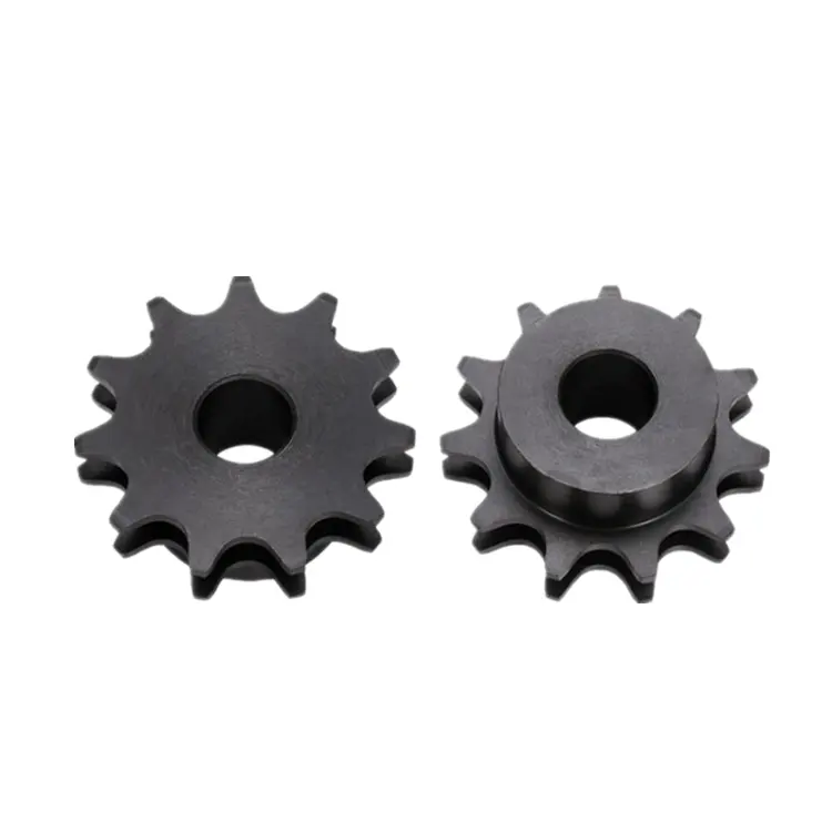
American standard chain sprocket with teeth hardened
With more than 15 years’ experience, high-precision equipment and strict management system, CIMO can provide sprockets for you with stable quality and best service.
| Item | Sprocket |
| Standard | DIN, KANA, ANSI, ISO, etc |
| Material | C45, stainless steel SS304 & SS316, Cast iron, etc |
| Bore | Pilot bore, finished bore, taper bore |
| Surface Treatment | Black oxided, Zinc plated, Electrophoresis, etc |
| Heat treatment | Teeth inductive hardened HRC45-50 |
| Process | Forging, Cutting, Hobbing teeth, CNC Lathe machining |
| European Type | 03B, 04B, 05B, 06B, 081B, 083B/084B, 085B, 086B, 08B, 10B, 12B, 16B, 20B, 24B, 28B, 32B |
| American Type | 25, 35, 40, 50, 60, 80, 100, 120, 140, 160, 200, 240 |
|
Taper bore sprockets |
|
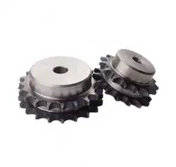
| Finished bore sprockets | |
|
Idler sprockets with ball bearing |
|
|
Double simplex sprockets |
|
|
Sprockets with split taper bushings |
|
|
Sprockets with QD bushings |
|
| Double sprockets for 2 single chains | |
|
Double pitch sprockets |
C2042, C2052, C2062, C2082, C2040, C2050, C2060, C2080 |
| Platewheels for Conveyor chain | 20x16mm, 30×17.02mm |
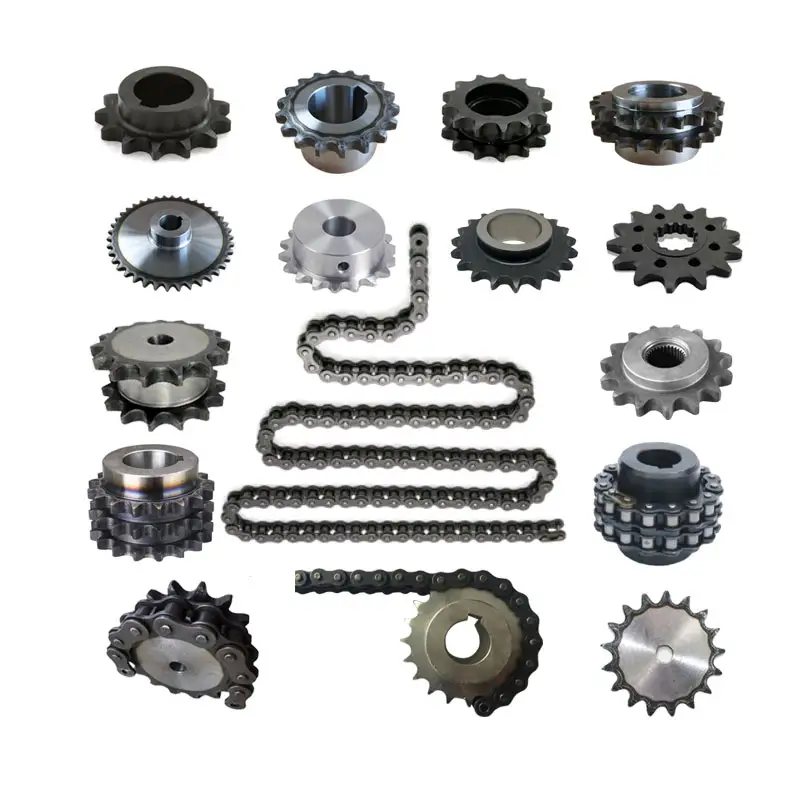
Detailed Photos
Workshop
Packaging & Shipping
Export wooden box
FAQ
Q1: Are you trading company or manufacturer ?
A: We are factory.
Q2: How long is your delivery time and shipment?
1.Sample Lead-times: 10-20 days
2.Production Lead-times: 30-45 days after order confirmed.
Q3: What is your advantages?
1. The most competitive price and good quality.
2. Perfect technical engineers give you the best support.
3. OEM is available.
| Standard Or Nonstandard: | Nonstandard |
|---|---|
| Application: | Motor, Electric Cars, Motorcycle, Machinery, Agricultural Machinery, Chain |
| Hardness: | Hardened Tooth Surface |
| Manufacturing Method: | Cut Gear |
| Toothed Portion Shape: | Sprocket |
| Material: | Steel C45 |
| Customization: |
Available
| Customized Request |
|---|
wheel sprocket System in Heavy Machinery and Industrial Equipment
Yes, a wheel sprocket system is commonly used in heavy machinery and industrial equipment for power transmission and motion control. The wheel sprocket configuration is a versatile and efficient method of transmitting rotational force between two shafts.
In heavy machinery and industrial equipment, the wheel is typically attached to one shaft, while the sprocket is mounted on another shaft. A chain or a toothed belt is wrapped around the wheel sprocket, connecting them. When the wheel is rotated, the chain or belt engages with the sprocket, causing the sprocket and the connected shaft to rotate as well. This mechanism allows the transfer of power from one shaft to the other, enabling various components and parts of the machinery to function.
Common applications of the wheel sprocket system in heavy machinery include:
- Construction Machinery: Wheel loaders, excavators, cranes, and other construction equipment often use wheel sprocket systems for efficient power transmission in various moving parts.
- Material Handling Equipment: Forklifts, conveyor systems, and other material handling equipment utilize wheel sprocket configurations to move goods and materials smoothly and reliably.
- Mining Equipment: Mining machinery, such as drilling rigs and conveyors, often incorporate wheel sprocket assemblies for power transmission in challenging environments.
- Agricultural Machinery: Tractors, combines, and other agricultural equipment use wheel sprocket systems to drive various components like wheels and harvesting mechanisms.
- Industrial Robotics: Robots and automated systems in manufacturing often utilize wheel sprocket setups for precise motion control and efficient power transmission.
One of the key advantages of the wheel sprocket system is its ability to handle heavy loads and transmit power over long distances. It is a reliable and cost-effective method of power transmission in various industrial settings. However, proper maintenance and alignment are crucial to ensuring the system’s optimal performance and longevity.
Overall, the wheel sprocket system is a widely used and effective power transmission solution in heavy machinery and industrial equipment, offering versatility and efficiency in a range of applications.
Inspecting a wheel sprocket for Wear and Tear
Regular inspection of the wheel sprocket is essential to ensure their proper functioning and to identify any signs of wear and tear. Here are the steps to inspect a wheel sprocket:
- Visual Inspection: Start by visually examining the wheel sprocket for any visible signs of wear, damage, or deformation. Look for cracks, chips, dents, or any irregularities on the surface of both components.
- Check for Misalignment: Verify that the wheel sprocket are properly aligned with each other. Misalignment can lead to accelerated wear and affect the overall performance of the system.
- Measure Wear: Use calipers or a wear gauge to measure the sprocket’s tooth profile and the wheel’s rolling surface. Compare these measurements with the original specifications to determine if significant wear has occurred.
- Inspect Teeth and Chain Engagement: If the wheel sprocket are part of a chain drive system, closely examine the sprocket teeth and chain engagement. Worn or elongated teeth can cause poor chain engagement and lead to premature failure.
- Lubrication: Check the lubrication of the wheel sprocket. Insufficient or excessive lubrication can cause increased friction, leading to wear and reduced efficiency.
- Bearing Condition: If the wheel is mounted on a shaft with bearings, inspect the bearings for any signs of wear, noise, or rough movement. Properly functioning bearings are crucial for the smooth operation of the system.
- Inspect Mounting Hardware: Ensure that all nuts, bolts, and other mounting hardware are securely tightened. Loose fasteners can cause vibration and misalignment issues.
- Check for Contaminants: Remove any debris, dirt, or foreign particles that may have accumulated on the wheel or sprocket. Contaminants can accelerate wear and damage the components.
- Replacement or Maintenance: Based on the inspection results, determine if any parts need replacement or if maintenance is required. Address any issues promptly to prevent further damage and maintain the system’s performance.
Regularly scheduled inspections and maintenance can help prolong the lifespan of the wheel sprocket assembly, optimize performance, and ensure the safety of the mechanical system.
Calculating Gear Ratio for a wheel sprocket Setup
In a wheel sprocket system, the gear ratio represents the relationship between the number of teeth on the sprocket and the number of teeth on the wheel. The gear ratio determines the speed and torque relationship between the two components. To calculate the gear ratio, use the following formula:
Gear Ratio = Number of Teeth on Sprocket ÷ Number of Teeth on Wheel
For example, if the sprocket has 20 teeth and the wheel has 60 teeth, the gear ratio would be:
Gear Ratio = 20 ÷ 60 = 1/3
The gear ratio can also be expressed as a decimal or percentage. In the above example, the gear ratio can be expressed as 0.3333 or 33.33%.
It’s important to note that the gear ratio affects the rotational speed and torque of the wheel sprocket. A gear ratio greater than 1 indicates that the sprocket’s speed is higher than the wheel’s speed, resulting in increased rotational speed and reduced torque at the wheel. Conversely, a gear ratio less than 1 indicates that the sprocket’s speed is lower than the wheel’s speed, resulting in decreased rotational speed and increased torque at the wheel.
The gear ratio is crucial in various applications where precise control of speed and torque is required, such as bicycles, automobiles, and industrial machinery.


editor by CX 2023-08-18